|
|
| |
|

|
|
|
|
| |
|

|
| |
 |
Wire And Reg
|
|
|
Well I had this doubt when I was learning Verilog: What is the difference between reg and wire? Well I won't tell stories to explain this, rather I will give you some examples to show the difference. |
| |
|

|
|
|
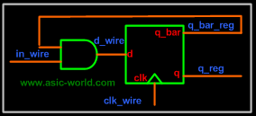
From the college days we know that wire is something which connects two points, and thus does not have any driving strength. In the figure below, in_wire is a wire which connects the AND gate input to the driving source, clk_wire connects the clock to the flip-flop input, d_wire connects the AND gate output to the flip-flop D input. |
| |
|

|
|
|
 |
| |
|

|
|
|
There is something else about wire which sometimes confuses. wire data types can be used for connecting the output port to the actual driver. Below is the code which when synthesized gives a AND gate as output, as we know a AND gate can drive a load. |
| |
|

|
|
|
 1 module wire_example( a, b, y);
 2   input a, b;
 3   output y;
 4
 5   wire a, b, y;
 6
 7   assign y = a & b;
 8
 9 endmodule
You could download file wire_example.v here
|
| |
|

|
|
|
SYNTHESIS OUTPUT |
| |
|

|
|
|
 |
| |
|

|
|
|
What this implies is that wire is used for designing combinational logic, as we all know that this kind of logic can not store a value. As you can see from the example above, a wire can be assigned a value by an assign statement. Default data type is wire: this means that if you declare a variable without specifying reg or wire, it will be a 1-bit wide wire. |
| |
|

|
|
|
Now, coming to reg data type, reg can store value and drive strength. Something that we need to know about reg is that it can be used for modeling both combinational and sequential logic. Reg data type can be driven from initial and always block. |
| |
|

|
|
|
Reg data type as Combinational element |
| |
|

|
|
|
  1 module reg_combo_example( a, b, y);
  2 input a, b;
  3 output y;
  4
  5 reg   y;
  6 wire a, b;
  7
  8 always @ ( a or b)
  9 begin
 10   y = a & b;
 11 end
 12
 13 endmodule
You could download file reg_combo_example.v here
|
| |
|

|
|
|
SYNTHESIS OUTPUT |
| |
|

|
|
|
 |
| |
|

|
|
|
This gives the same output as that of the assign statement, with the only difference that y is declared as reg. There are distinct advantages to have reg modeled as combinational element; reg type is useful when a "case" statement is required (refer to the Verilog section for more on this). |
| |
|

|
|
|
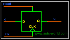
To model a sequential element using reg, we need to have edge sensitive variables in the sensitivity list of the always block. |
| |
|

|
|
|
Reg data type as Sequential element |
| |
|

|
|
|
  1 module reg_seq_example( clk, reset, d, q);
  2 input clk, reset, d;
  3 output q;
  4
  5 reg   q;
  6 wire clk, reset, d;
  7
  8 always @ (posedge clk or posedge reset)
  9 if (reset) begin
 10   q <= 1'b0;
 11 end else begin
 12   q <= d;
 13 end
 14
 15 endmodule
You could download file reg_seq_example.v here
|
| |
|

|
|
|
SYNTHESIS OUTPUT |
| |
|

|
|
|
 |
| |
|

|
|
|
There is a difference in the way we assign to reg when modeling combinational logic: in this logic we use blocking assignments while modeling sequential logic we use nonblocking ones. |
| |
|

|
| |
|

|
| |
|

|
|
|
|
| |
|

|
|
|
|
|

|

|

|
|

|
|
Copyright © 1998-2025 |
Deepak Kumar Tala - All rights reserved |
|
Do you have any Comment? mail me at:deepak@asic-world.com
|
|
|