|
|
| |
|

|
|
|
|
| |
|

|
| |
 |
Introduction
|
|
|
There are times when a designer needs to interface two systems working at two different clocks. This interfacing is difficult in the sense that design becomes asynchronous at the boundary of interface, which results in setup and hold violation, metastability and unreliable data transfers. So we need to go out for special design and interfacing techniques. |
| |
|

|
|
|
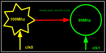
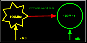
Any two systems are considered asynchronous to each other: |
| |
|

|
|
|
When they operate at two different frequency |
|
|
 |
| |
|

|
|
|
When they operate at same frequency, but at two different clock phase angles |
|
|
 |
| |
|

|
|
|
Here we have two systems, which are asynchronous in nature to each other. In such a case if we need to do data transfer, there are very few methods to achieve this: |
| |
|

|
|
|
- Handshake Signaling method.
- Asynchronous FIFO.
|
| |
|

|
|
|
|
| |
|

|
| |
 |
Handshake Signaling
|
|
|
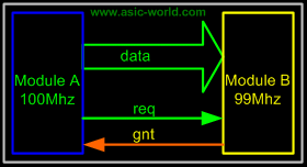
In this method the system (module) A sends data to system/module B based on the handshake signals ack and req signals. The protocol for this uses the same old method that is found with 8155 chip used with 8085. |
| |
|

|
|
|
 |
| |
|

|
|
|
Protocol |
|
|
- Transmitter asserts the req (request) signal, asking the receiver to accept the data on the data bus.
- Receiver asserts the ack (acknowledge) signal, asserting that it has accepted the data.
|
| |
|

|
|
|
 |
| |
|

|
|
|
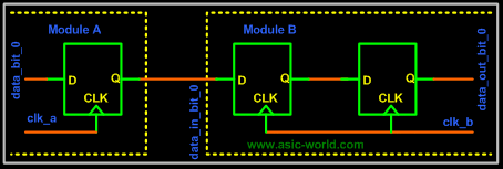
This method is straightforward, but it too has got loop holes: when system B samples the systems A's req line and System A samples system B's ack line, they are done with respect to their internal clock, so there will be setup and hold time violation. To avoid this we go for double or triple stage synchronizers, which increase the MTBF and thus are immune to metastability to a good extent. The figure below shows how this is done with respect to the above example. |
| |
|

|
|
|
 |
| |
|

|
|
|
If we do the double or triple stage synchronizing, then the transfer rate comes down, due to the fact that a lot of clock cycles are wasted just handshaking. |
| |
|

|
|
|
 |
| |
|

|
|
|
Sometimes it is good to synchronize the data also to be double sure, but normally we don't do this, as it takes a lot of logic and what we gain is very small. The figure below shows one such case (there is no difference between circuits shown for req and data, they are one and same). |
| |
|

|
|
|
 |
| |
|

|
| |
 |
Asynchronous FIFO
|
|
|
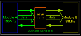
An Asynchronous FIFO has got two interfaces, one for writing the data into the FIFO and the other for reading the data out. It has got two clocks, one for writing and the other for reading. System A writes the data in the FIFO and System B reads out the data from it. To facilitate error free operations, we have FIFO full and FIFO empty signals. These signals are generated with respect to the corresponding clock. FIFO full signal is used by system A (as when FIFO is full, we don't want system A to write data into FIFO, this data will be lost), so it will be driven by the write clock. Similarly, FIFO empty will be driven by the read clock. Here read clock means system B clock and write clock means system A clock. |
| |
|

|
|
|
Asynchronous FIFO is used at places when the performance is a matter, when one does not want to waste clock cycles in handshake signals, when there is a lot of system resources available. |
| |
|

|
|
|
 |
| |
|

|
|
|
How to design an Asynchronous FIFO is not in the scope of this document, but what I would like to point out is that one should be careful with the generation of FIFO full and FIFO empty signals, as it may, in certain cases, cause metastability. |
| |
|

|
| |
|

|
| |
|

|
|
|
|
| |
|

|
|
|
|
|

|

|

|
|

|
|
Copyright © 1998-2025 |
Deepak Kumar Tala - All rights reserved |
|
Do you have any Comment? mail me at:deepak@asic-world.com
|
|
|